 : +86-139 0587 7291
 Anglais
 Espagnol
 Russe
Russe Français
 العربية
 Portugais du Brésil
 Ukraïnské
 turc
turc Polonais
 Néerlandais
 Italien
 Indonésien
 shérif
 اردو
اردو አማርኛ
አማርኛ Հայերեն
 ไทย
ไทย Mongol
 فارسی
فارسی Shqip
Shqip Élagueur

Explication des composants et de la structure interne du contacteur CA
Table des matières
BasculerAC contactor parts include the electromagnetic system, contact system, arc extinguishing components, and housing assembly that work together to control electrical circuits. Understanding each contactor diagram component helps with maintenance, troubleshooting, and proper installation.
What Are the Main AC Contactor Parts?
Every AC contactor contains four essential systems that enable electrical switching:
- Electromagnetic system (coil and iron core)
- Contact system (main and auxiliary contacts)
- Arc extinguishing system (arc suppression components)
- Auxiliary components (housing, springs, terminals)
Each AC contactor part serves a specific function in the switching operation.
What Does the Electromagnetic System Do?
The electromagnetic system contains the electromagnetic coil and iron core. When the electromagnetic coil is energized, it generates a magnetic field to attract the iron core action. This magnetic field magnetizes the iron core and generates electromagnetic suction, which overcomes the reaction force of the spring.
Common coil voltages include:
- 24V for control circuits
- 110V for some applications
- 220V and 380V for main power circuits
When the movable iron core and the static iron core are absorbed, the main contact connected to it is driven to close.
How Do the Contact Systems Work?
The contact system has the main contact and auxiliary contact. The main contact is used to connect and disconnect the main circuit and bears a large current. Main contacts handle different current levels like 10A, 20A, 40A and other specifications.
Auxiliary contact is mainly used for signaling in the control circuit. The auxiliary contact current is smaller compared to main contacts. They provide signals to indicate contactor position in your control system.
Why Do You Need Arc Extinguishing Components?
Arc extinguishing system is used to extinguish the arc generated when the contact breaks the circuit. This prevents damage to the contact from arc and avoids causing electrical accidents.
When contacts separate while carrying current, electrical arcing occurs that can weld contacts together or cause severe burning. The arc extinguishing system manages this arc to protect the contacts from damage during circuit breaking.
How Do You Read an AC Contactor Diagram?
Understanding contactor diagram symbols helps you wire and troubleshoot these devices correctly. Standard electrical symbols represent each component and connection point.
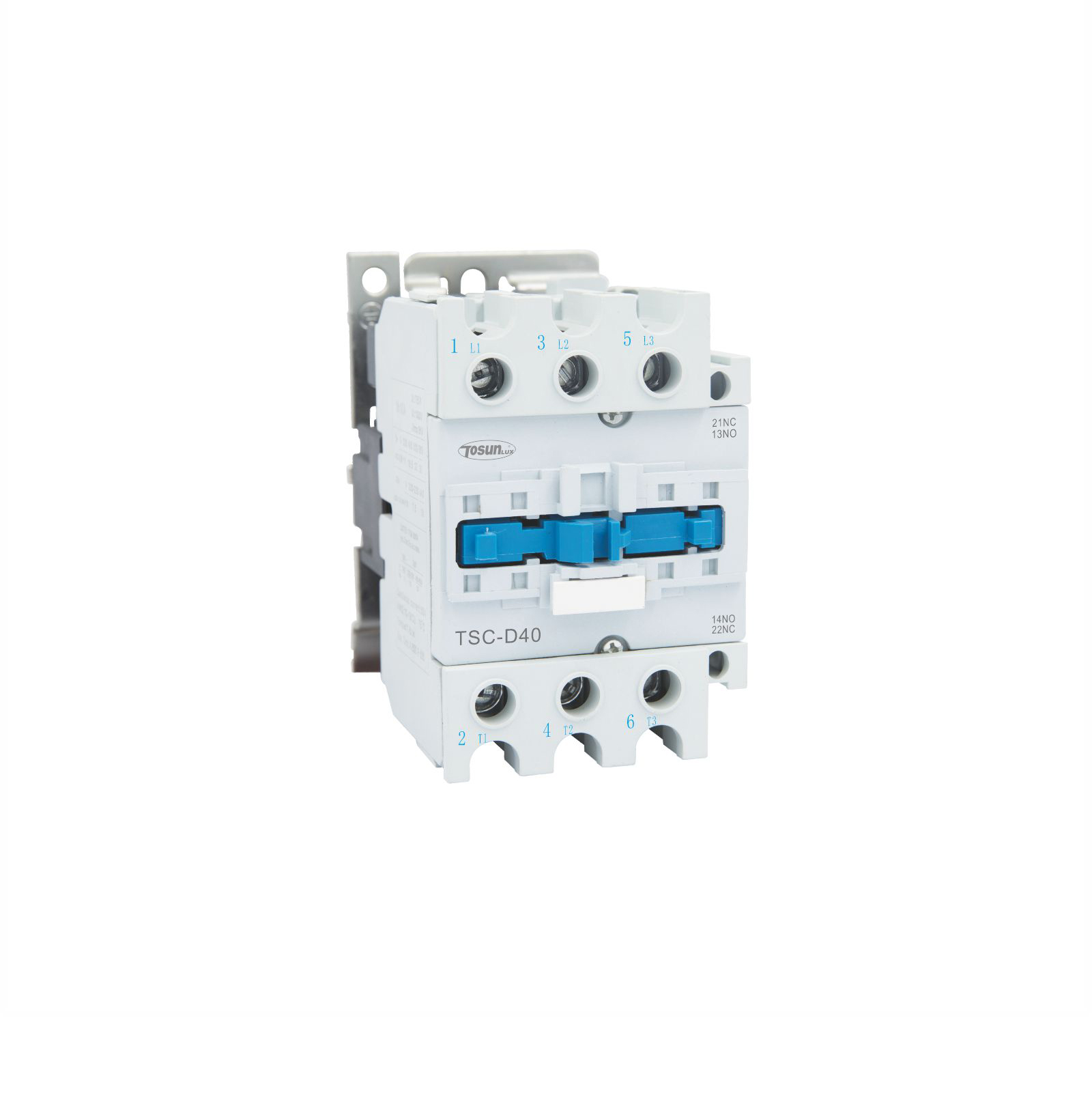
What Do the Terminal Markings Mean?
Coil terminals use A1 and A2 markings to identify electromagnetic coil connections. Main contact terminals use numbered pairs for three-phase applications:
- Main contacts: 1-2, 3-4, 5-6 (numbered pairs that operate together)
- Auxiliary normally open: 13-14, 23-24 (numbers ending in 3-4)
- Auxiliary normally closed: 11-12, 21-22 (numbers ending in 1-2)
- Coil connections: A1 and A2 terminals
These markings help you identify which terminals connect together during wiring.
How Do You Identify Contact Types?
Main contacts appear as heavy lines in contactor diagrams because they carry high current loads. Auxiliary contacts appear as lighter lines since they handle only control currents.
Contact symbols in diagrams:
- Normally open contacts show a gap between contact points
- Normally closed contacts show contact points touching
- Heavy lines indicate main contacts (high current)
- Light lines show auxiliary contacts (control current)
This helps you understand the default contact position when the coil is not energized.
What Are the Voltage and Current Ratings?
Every AC contactor part has specific ratings that determine safe operating limits:
- Rated voltage: Maximum voltage without insulation breakdown
- Rated current: Maximum continuous current through main contacts
- Coil voltage: Control circuit voltage (24V, 110V, 220V, 380V)
- Contact voltage: Main circuit voltage (220V, 380V, 660V)
Understanding these ratings prevents equipment damage and ensures safe operation.
What Does Rated Voltage Mean?
Rated voltage refers to the maximum voltage the contactor can handle without insulation breakdown. Main contact voltage ratings like 220V, 380V, or 660V indicate the circuit voltages they can safely switch. The electromagnetic coil has its own voltage rating that must match your control circuit voltage.
Using incorrect voltages damages contactors quickly. A 24V coil connected to 220V will burn out immediately while a 220V coil on 24V won’t provide enough force to close the contacts reliably.
How Do You Determine Current Requirements?
Rated current indicates the maximum continuous current the main contacts can carry without overheating. Common ratings include 10A, 20A, 40A, and higher values for industrial applications. Contact material, contact area, and heat dissipation determine these current limits.
Select contactor current ratings at least 25% higher than your actual load current to ensure reliable operation and longer contact life. Heavy inductive loads like motors may require even higher safety margins.
How Does an AC Contactor Work?
The AC contactor working principle operates like an electromagnetically controlled switch that responds to control signals. Each component plays a specific role in the switching operation.
What Happens When You Energize the Coil?
When you apply rated voltage to the electromagnetic coil, current flows through the coil windings and creates a magnetic field. This magnetic field magnetizes the iron core and generates electromagnetic attraction that overcomes the spring force.
The movable armature pulls toward the stationary core, mechanically operating the attached contact assembly. Main contacts close to complete your load circuit while auxiliary contacts change position for control signaling.
What Occurs During De-energization?
When you remove power from the electromagnetic coil, the magnetic field collapses and electromagnetic attraction disappears. Spring force pushes the armature back to its rest position, opening the main contacts and returning auxiliary contacts to their normal positions.
The arc extinguishing system manages any electrical arc that forms during contact separation to protect the contacts from damage. For comprehensive information about contactor operation and applications, see the ultimate guide to AC contactor which covers selection, installation, and maintenance details.
What Components Provide Physical Protection?
The housing and auxiliary components protect internal parts from environmental damage while providing safe access for connections and maintenance.
How Does the Housing Assembly Work?
The protective housing shields internal components from dust, moisture, and physical damage while providing electrical insulation between live parts. Mounting provisions allow secure installation in electrical panels or on mounting rails.
Terminal blocks provide safe connection points for field wiring without exposing live electrical parts. Proper housing ratings ensure safe operation in various environmental conditions.
What Role Do Springs Play?
Return springs provide the mechanical force needed to open contacts when the electromagnetic coil de-energizes. Spring tension must overcome contact pressure and any mechanical friction in the contact system.
Contact springs also maintain proper contact pressure when the contactor is energized to ensure low resistance electrical connections. Proper spring adjustment prevents contact bouncing and ensures reliable operation.
FAQ
What is the most important AC contactor part?
The electromagnetic coil is the most critical component since it controls all switching operations. Coil failure prevents the contactor from operating at all.
How do you identify failed contactor parts?
Visual inspection reveals burnt contacts, melted housing, or damaged coils. Electrical testing with a multimeter can verify coil resistance and contact continuity.
Can you replace individual AC contractor parts?
Some contactors allow replacement of contact assemblies, but coil replacement usually requires complete contactor replacement due to assembly complexity.
Conclusion
AC contactor parts work together through electromagnetic, contact, and arc extinguishing systems to provide reliable circuit switching. Understanding the contactor diagram and component functions helps with proper selection, installation, and maintenance. Each component serves a specific purpose in the overall switching operation.
Tél. : +86-577-88671000
E-mail: ceo@tosun.com
Skype : àsunelectric
Wechat : +86-139 6881 9286
WhatsApp : +86-139 0587 7291
Adresse : Salle n° 1001 Wenzhou Fortune Center, Station Road, Wenzhou, Chine
DEMANDER UN DEVIS
Envoyez-nous un WhatsApp