: +86-139 0587 7291
 English
 Español
 Русский
 Français
 العربية
 Português do Brasil
 Українська
 Türkçe
 Polski
 Nederlands
 Italiano
 Bahasa Indonesia
 हिन्दी
 اردو
اردو አማርኛ
አማርኛ Հայերեն
 ไทย
ไทย Монгол
 فارسی
فارسی Shqip
Shqip Ελληνικά

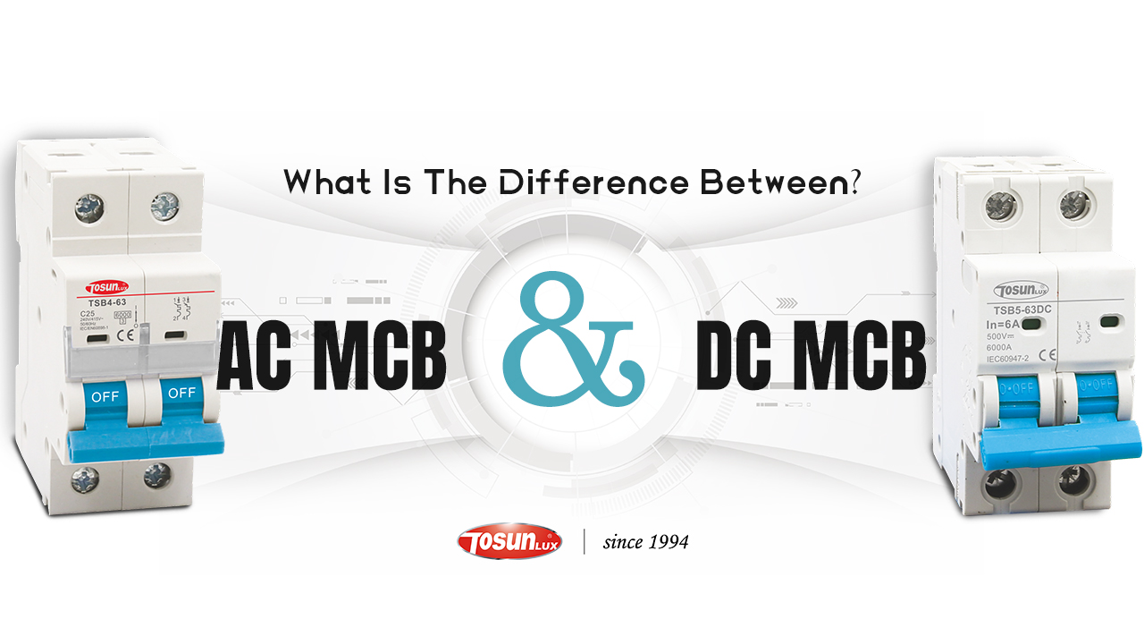
What Is the Difference Between AC MCB And DC MCB?
26th Mar 2026
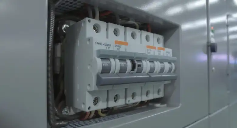
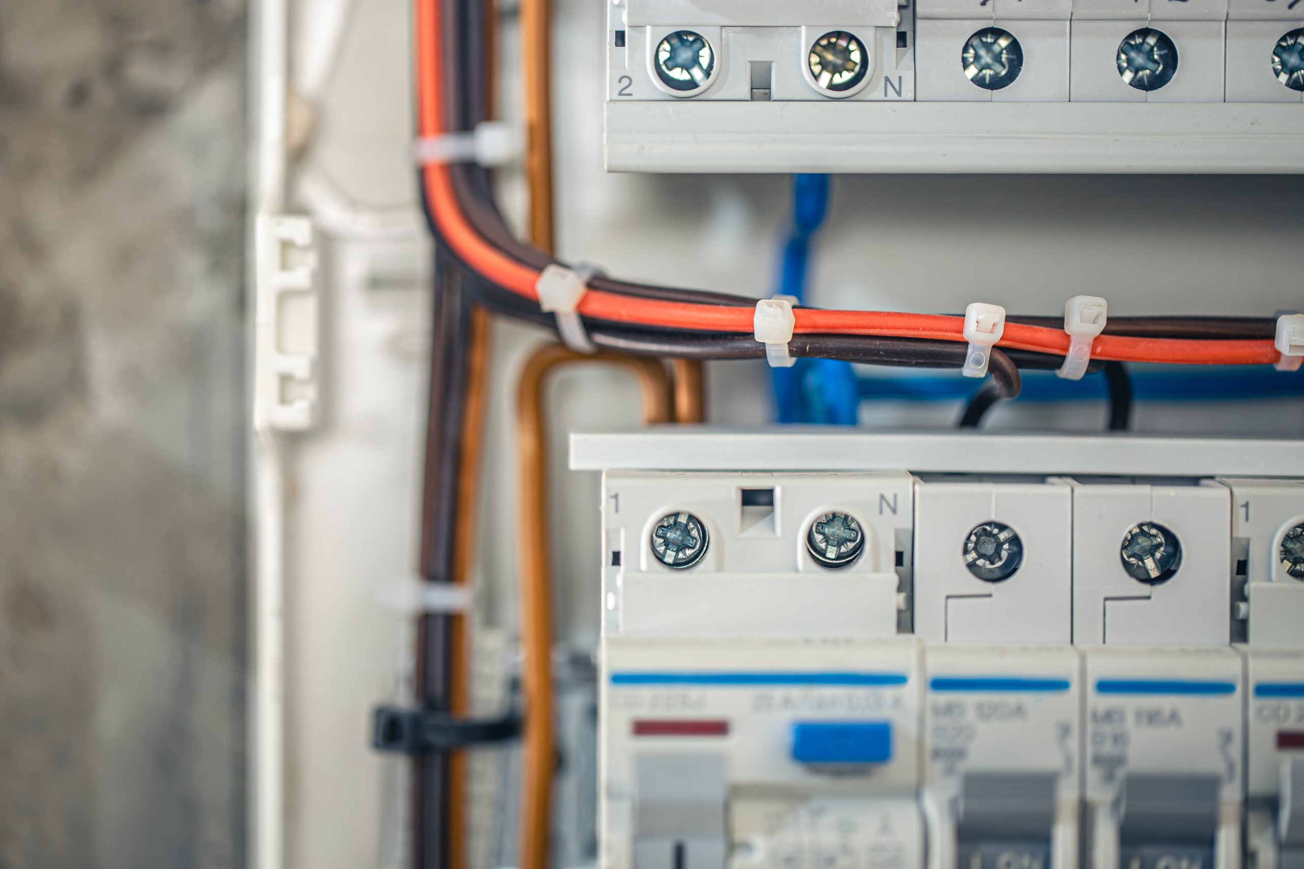
AC MCBs and DC MCBs may look similar, but they are not designed for the same electrical conditions. The difference is not only the current type. Arc interruption, polarity, breaking behavior, and application environment all affect whether the breaker is suitable for the circuit. For buyers, the most important point is simple: an AC breaker should not be selected for a DC circuit just because the current rating looks similar. This guide explains the practical difference and when each type should be used. Key Differences Between AC MCB and DC MCB The following table highlights the main differences between AC and DC MCBs based on structure, applications, and technical specifications: Feature AC MCB DC MCB Current Type Alternating Current (AC) Direct Current (DC) Arc Suppression Handles arc interruption more easily Requires larger arc suppression mechanism Applications Used in homes, offices, and AC circuits Suitable for solar, battery, and DC circuits Breaking Capacity Lower, due to easier arc suppression in AC Higher, to manage steady DC current Polarity Sensitivity Not polarity sensitive Polarity sensitive Lifespan Longer in AC due to arc dissipation Shorter as DC arcs wear components faster How to Choose the Right Breaker for the Application Choose an AC MCB for standard low-voltage AC distribution circuits in homes, commercial buildings, and general industrial panels. Choose a DC MCB for solar applications, battery energy storage systems, DC combiner boxes, and other circuits where the load and source are both direct current. Before ordering, confirm the system voltage, current, number of poles, installation layout, and the […]
Read More